
Cartridges · count the parallel area
Cartridge & housing quantity calculator
Convert design flow and a manufacturer-approved element flow into cartridges per stage, housings per stage and total installed cartridges—while keeping parallel capacity separate from series filtration.
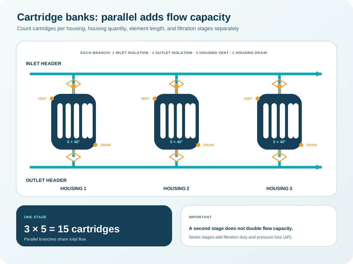
Installed arrangement
3 × 5-round
Series rule:
Parallel versus series
Only parallel elements add flow capacity.
Every series stage receives the full design flow and its clean/dirty pressure drop adds to the system. A second polishing stage may improve retention; it does not double throughput.
Before ordering
Micron, chemistry and ΔP still choose the cartridge.
- Use the exact element’s flow/ΔP curve and viscosity correction.
- Check housing pressure, seal and material compatibility.
- Set a differential-pressure changeout limit.
- Do not assume 10-inch-equivalent capacity without manufacturer support.
Check the assumptions
Method and primary references
The equations are shown so the result can be checked. Product data and site conditions still govern final selection.
- Pall Filter Sizing GuideFlow-per-cartridge and pressure-drop sizing principles.
- Pentair AquaLine ALN10–60BExample 60-inch high-flow element clean-water ΔP curve and operating limits.
- Eaton Cartridge HousingsParallel housing and industrial configuration context.
From answer to equipment
Bring the duty point, not just a product name.
Watermart can check the calculation against the actual water analysis, pressure, valve, pump and installation constraints.
Discuss this calculation →Educational preliminary calculation—not a stamped design, quotation, or treatment-performance guarantee.