
Granular media · service and backwash
Filter service, series & backwash calculator
Choose a controlled service rate and a controlled backwash target. Then test single, parallel or series arrangements—including the temporary loading when one series vessel backwashes through another.
Controlled duty point
Coconut-shell activated carbon
Action:
What to do when flows do not match
Control the flow; do not average an impossible range.
Set the service limit with a flow controller, VFD or balancing valve, or add vessel area in parallel. Set backwash with the correct DLFC/orifice, VFD or control valve. Excess backwash can lose media; insufficient backwash leaves the bed dirty.
Pump-curve checkpoint
The pump must meet one exact target at the real head.
Plot the selected backwash flow against total dynamic head: static lift, pipe/fittings, valve or DLFC, distributor/underdrain, dirty bed and drain backpressure. Verify the pump/system-curve intersection, runout, NPSH and valve capacity.
- Use the exact media expansion curve at actual temperature.
- Backwash one vessel at a time unless explicitly designed otherwise.
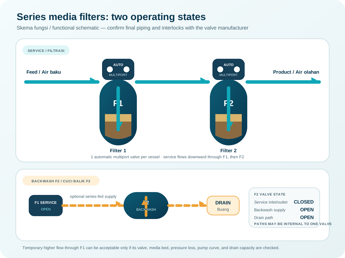
- Prefer a treated-water header or tank for series systems.
Series is not parallel
Two series filters still carry the same 3 m³/h.
Series stages add treatment barriers and pressure loss, not flow capacity. If downstream backwash water must pass through the upstream vessel, that upstream vessel temporarily sees the downstream backwash flow as service flow. This can be acceptable briefly only after checking dirty-bed pressure loss, valve/internals, available inlet pressure and water suitability.
Worked example · 3 m³/h
24″ GAC stage × 2 in series
At 5 GPM/ft², the theoretical diameter is about 22 in, so a 24 in vessel is hydraulically conservative only. Its actual loading at 3 m³/h is 4.20 GPM/ft². GAC backwash at the selected 10 GPM/ft² is 7.14 m³/h and uses 1.19 m³ in 10 minutes. Passing that through the upstream 24 in vessel gives 10 GPM/ft²—2.38× normal service loading. Final GAC bed volume must still meet EBCT, contaminant load and breakthrough criteria.
Check the assumptions
Method and primary references
The equations are shown so the result can be checked. Product data and site conditions still govern final selection.
- Clack Anthracite #1Service 5+; backwash 12–18 GPM/ft²; 20–40% expansion.
- Clack Coconut-shell HACService 5; backwash 10–12 GPM/ft²; 30–40% expansion.
- Clack Filter-AgNominal service 5; backwash 8–10 GPM/ft².
- Clack CalciteService 3–6; backwash 8–12 GPM/ft².
- Inversand GreensandPlus TDSService 2–12; minimum backwash 12 GPM/ft² at 12.8°C; use expansion curve.
From answer to equipment
Bring the duty point, not just a product name.
Watermart can check the calculation against the actual water analysis, pressure, valve, pump and installation constraints.
Discuss this calculation →Educational preliminary calculation—not a stamped design, quotation, or treatment-performance guarantee.