Quick answer: preliminary FRP vessel diameter comes from design service flow divided by the selected filtration rate, then converted from area to diameter. Check media-bed depth, freeboard, backwash flow, pressure, and control-valve flow limits together. This worksheet establishes a design basis; it does not replace final media, valve, and vessel datasheets.
Start with one clear duty flow: average, peak, or the capacity required while another unit is unavailable. PT Watermart Perkasa can match the result to FRP vessels, filter media, and automatic control valves once raw-water data, treated-water target, and installation conditions are available.
Updated 2 August 2026: this worksheet now adds manufacturer backwash-rate comparisons, valve-capacity checks, distributor limits, and a commissioning record.
Inputs required before sizing
Do not begin with a vessel size that happens to be in stock. Record water quality, hydraulic duty, and physical limits so neither filtration nor backwash rate is chosen from pipe size alone.
| Symbol | Input | Unit | How to set it |
|---|---|---|---|
| Qs | Design service flow | m³/h | Peak flow the operating filter must actually deliver |
| Vs | Design filtration rate | m³/m²/h | Media guidance and influent quality; not one universal value |
| Hb | Media-bed depth | m | Media datasheet, treatment duty, and underdrain arrangement |
| Fbw | Backwash rate | m³/m²/h | Media datasheet at design water temperature for required bed expansion |
| Qbw | Available backwash flow | m³/h | Pump curve, actual pressure, piping, and concurrent demand |
| Hf | Available freeboard | m | Shell height above media after allowing for backwash expansion |
| Pv | Design pressure and temperature | bar; °C | Maximum system conditions and vessel, valve, and fitting ratings |
Also obtain turbidity, iron/manganese, organic matter, particle size, pH, operating hours, and treated-water target. These inputs determine pretreatment need, likely bed fouling rate, and whether one vessel provides sufficient availability.
FRP vessel diameter and filter-area worksheet
Select Vs from media documentation and influent conditions, then calculate using m³/h and m² consistently.
- Calculate minimum filter area.
A = Qs ÷ Vs - Calculate initial hydraulic diameter.
D = √(4 × A ÷ π) - Select an available vessel diameter equal to or above D. Do not round down, because actual filtration rate rises.
- Calculate actual area from the selected diameter.
Aactual = π × D² ÷ 4 - Calculate actual filtration rate.
Vs,actual = Qs ÷ Aactual - Check bed height and freeboard. Internal vessel height must accommodate the underdrain, Hb, Hf, and connection allowance; freeboard must remain adequate when the bed expands during backwash.
| Check | Formula or evidence | Pass condition |
|---|---|---|
| Service area | Aactual = π × D² ÷ 4 | Actual area is not below minimum area |
| Actual filtration rate | Qs ÷ Aactual | Does not exceed media and influent limit |
| Media volume | Aactual × Hb | Matches media arrangement and vessel volume |
| Expansion space | Shell height less underdrain and Hb | Meets media-datasheet expansion allowance |
| Pressure/temperature | Vessel and valve datasheets | Every component rating exceeds design condition |
Backwash and control-valve worksheet
Do not size backwash from service rate. Use the media manufacturer’s Fbw at design water temperature, then calculate the required flow for the selected vessel.
- Calculate required backwash flow.
Qbw,required = Aactual × Fbw - Compare it with available backwash flow. Pump and pipework must deliver
Qbw,requiredat the pressure remaining at the vessel, not merely at an unloaded pump-flow point. - Check valve limits. The control-valve datasheet must cover service flow, backwash flow, port size, pressure drop, operating pressure, and cycle sequence for the configuration.
- Check drain and water source. The drain must receive backwash flow; the tank or source must supply one cycle without disrupting the service that remains online.
| Item | Value to enter | Decision |
|---|---|---|
| Selected vessel diameter | m | |
| Actual area, Aactual | m² | |
| Media backwash rate, Fbw | m³/m²/h | |
| Required backwash flow | Aactual × Fbw m³/h | |
| Pump flow available at duty point | m³/h | Confirm against pump curve |
| Control-valve backwash limit | m³/h | Refer to selected model datasheet |
| Drain capacity | m³/h | Must not restrict required Qbw |
Test manufacturer backwash rates against the selected valve
Generic media guidance and product-specific data can differ. The Pentair Logix Magnum manual uses 10 gpm/ft² (about 24.5 m³/m²/h) as a preliminary table value for Birm, greensand, and carbon at 10°C water temperature and 50% expansion. The Clack Birm product page reviewed on 2 August 2026 lists 12–18 gpm/ft² (about 29.3–44.0 m³/m²/h), minimum freeboard equal to 50% of bed depth, and 20–40% bed expansion. Do not average the sources: the specific media, design temperature, expansion target, and process-vendor approval must set the final value.
Use the worked example’s 1.13 m² actual area to expose the hydraulic gate:
| Check basis for a 1.20 m vessel | Calculation | Result |
|---|---|---|
| Pentair generic media table, 10 gpm/ft² | 1.13 × 24.5 | 27.7 m³/h backwash |
| Clack Birm, 12–18 gpm/ft² | 1.13 × 29.3–44.0 | 33.1–49.7 m³/h backwash |
| Pentair Autotrol Magnum | Valve-only rating at 25 psi (1.72 bar) pressure drop | 20.2 m³/h backwash |
The result is unambiguous: the single 1.20 m vessel in this example needs more backwash flow than that valve rating, even under the lower generic media value. Longer backwash at insufficient flow is not the fix. Reassess multiple vessels, an external valve/manifold, pump, pipework, distributor, and drain; then recalculate availability and one-unit-at-a-time backwash sequencing. A valve-only rating also does not prove field flow because pipe, distributor, bed, and drain losses remain.
Worked preliminary example: 10 m³/h filter
This example shows the calculation order; it does not recommend a media rate. Suppose service demand is 10 m³/h and selected media/process information sets an initial rate of 10 m³/m²/h. Minimum area is 10 ÷ 10 = 1.00 m²; hydraulic diameter is √(4 × 1.00 ÷ π) = 1.13 m.
If the available vessel diameter is 1.20 m, actual area is π × 1.20² ÷ 4 = 1.13 m² and actual service rate is 10 ÷ 1.13 = 8.84 m³/m²/h. With a 0.80 m media bed, media volume is about 1.13 × 0.80 = 0.90 m³. Do not infer backwash rate from this example: enter Fbw from the media datasheet, multiply it by 1.13 m², then check pump, valve, drain, and freeboard.
Pre-purchase vessel and control-valve checklist
- Raw-water analysis and treated-water target establish the filter duty and pretreatment need.
- Service flow accounts for operating hours, peak flow, and capacity while one unit is unavailable.
- Filtration and backwash rates come from media documentation or approved design at relevant water temperature.
- Vessel diameter is rounded up from hydraulic diameter and actual rate is recalculated.
- Internal height allows for underdrain, full media bed, and freeboard during backwash expansion.
- Pump, pipework, valve, and drain can handle backwash flow at the actual duty point.
- Pressure, temperature, ports, connections, and internal distributor suit the final arrangement.
- Valve sequence—service, backwash, slow rinse, and fast rinse where used—matches the process and available water.
- Layout provides access for media loading, valve replacement, sampling, and maintenance.
Distributor, nozzle, and commissioning record
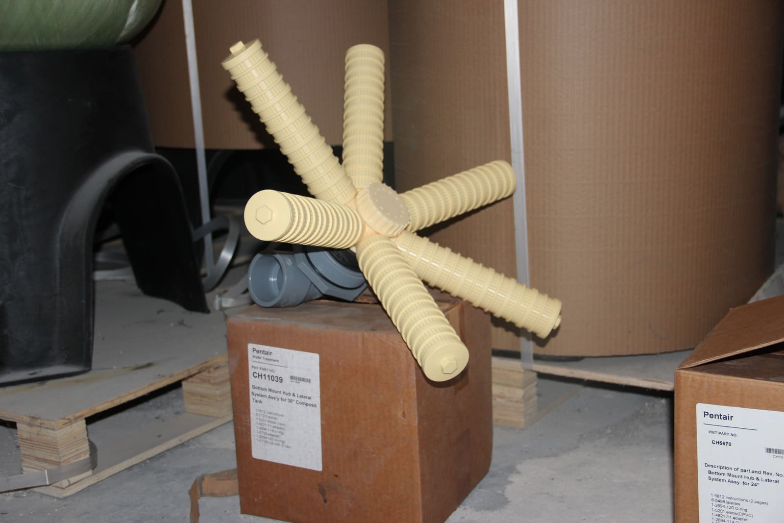
An adequately sized control valve can still fail to expand the bed if the riser, hub-and-lateral, top strainer, or drain is the bottleneck. Match vessel opening, riser size, media-retaining slot, open area, seals, and assembly drawing. Use the Pentair filter-nozzle and distributor selection guide to prepare that data; do not select internals from outside diameter or a photograph.
| Commissioning test | Data to record | Project-defined acceptance criterion |
|---|---|---|
| Pre-media inspection | Vessel/valve model, opening, riser, hub, lateral/nozzle, slot, seals, and drawing revision | All part numbers and dimensions match; no cracked, loose, or altered component |
| Initial fill and wetting | Media type, batch, volume, each layer depth, support bed, water level, and wetting time | Media arrangement and freeboard match final data |
| Service at minimum, normal, and peak flow | Flow, inlet/outlet pressure, differential pressure, filtrate quality, and media leakage | Actual rate, pressure drop, filtrate quality, and integrity remain inside project limits |
| Backwash and rinse | Actual flow, temperature, differential pressure, bed expansion, duration, drain clarity, and media carry-over | Expansion target is reached without media loss; drain and water source do not restrict flow |
| Control-valve sequence | Service/backwash/rinse position, cycle time, interlocks, alarms, and power-loss response | Every position and fallback matches the approved cause-and-effect |
| Return-to-service baseline | Clean differential pressure, flow, filtrate sample, valve setting, and operator | Signed baseline is available for future operation and maintenance comparisons |
Handoff to water-filter components
Send the completed worksheet, water analysis, PFD or layout, available pressure, and pump curve to PT Watermart Perkasa. These data support a checkable selection of FRP vessels for water filtration, filter media, control valves, and supporting components.
Where filtration is RO pretreatment, also use the RO membrane and pressure-vessel sizing guide. Procurement must still use final model numbers and datasheets for every component.
Sources
- Watermart FRP vessel page, for available vessel sizes and product configurations.
- Watermart filter-media page, for connecting the media duty to required design inputs.
- Watermart control-valve page, for selecting a model from verified flow and cycle data.
- Pentair Logix Magnum IT/Cv manual, for preliminary backwash tables by media, temperature, vessel diameter, and expansion.
- Clack Birm operating conditions, for the product’s bed depth, freeboard, service/backwash rate, and expansion.
- Pentair Autotrol Magnum specification sheet, for valve-only flow and the associated pressure drop.

.png)