
RO membrane damage cannot be diagnosed from pressure or low production alone. Compare normalized permeate flow, normalized salt passage, and each stage’s differential pressure with the commissioning baseline. Lower normalized flow with rising differential pressure points towards fouling; a sudden salt-passage increase can indicate oxidation, seal leakage, or physical damage. Isolate product water until the cause and quality are verified.
Updated 3 August 2026: diagnostic matrix, isolation evidence, lead-tail inspection, and CIP or replacement criteria added.
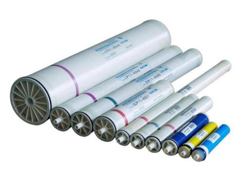
Initial RO Membrane Diagnosis from Operating Data
Actual data must be normalized for feed temperature, salinity, pressure, and recovery with the membrane manufacturer’s software or method. Colder water can reduce production without fouling, while changing feed salinity shifts permeate conductivity. Establish the baseline after stable commissioning and do not compare two different operating conditions as though they were equivalent.
| Pattern against baseline | Hypothesis to test | Evidence that separates the causes |
|---|---|---|
| Normalized permeate flow falls and differential pressure rises, especially in the first stage | Particulate, colloidal, biological, or feed-spacer fouling | SDI15/turbidity, cartridge differential pressure, pretreatment inspection, microbiology/TOC trend, and foulant analysis where available |
| Normalized permeate flow falls without a proportional differential-pressure rise | Surface scaling, compaction, or an incorrect normalization input | Scaling ions and recovery, antiscalant/pH history, temperature, net driving pressure, and deposit inspection |
| Normalized salt passage rises sharply while differential pressure stays relatively stable | Polyamide oxidation, O-ring/interconnector leak, damaged element, or telescoping | Chlorine/ozone/ORP history, conductivity profiling by vessel, integrity test, and seal/element condition |
| Differential pressure rises suddenly after startup or pipe work | Foreign material, cartridge bypass, incorrect valve position, water hammer, or wrong element loading | Startup record, cartridge/housing inspection, element order, thrust ring, interconnector, and pressure alarms |
| Poor quality appears in only one vessel or stage | Local seal, element, probe, or permeate-pipe issue | Instrument calibration, per-vessel sampling, probing, and position changes only under an approved investigation procedure |
| Every train changes at the same time | Shared feedwater, pretreatment, dosing, temperature, or instrument change | Raw-water results, dosing log, shared-sensor calibration, common-header valves, and plant event log |
Do not label a membrane “ruptured” because one TDS meter reads high. Confirm calibration, sample point, temperature, recovery, and multi-parameter trends. The SWRO flow-balance and baseline guide shows which feed-permeate-concentrate data should close before diagnosis.
Understanding of Reverse Osmosis Membrane
A reverse osmosis membrane is a separation barrier that receives pressurized feedwater and produces permeate and concentrate. In a spiral-wound element, the membrane sheet, feed spacer, permeate carrier, glue line, interconnector, O-rings, and pressure vessel work as one system. Product quality can deteriorate while the membrane sheet remains intact if a seal or permeate connection leaks.
Polyamide membranes reject many dissolved constituents, but membrane selection alone does not establish drinking-water acceptance. Pretreatment, operation inside manufacturer limits, sanitation, post-treatment, storage, representative sampling, and laboratory verification are still required. For procurement or replacement, match feedwater and duty to the reverse osmosis membrane range, not only to element diameter.
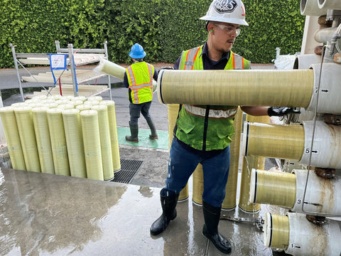
Common and Specific Causes of Damage to RO Membranes
Distinguish between deposits that may be cleaned, irreversible chemical change, and a mechanical or sealing failure. One element can show more than one mechanism, such as organic fouling followed by biofouling or scaling after an antiscalant failure.
Common Causes of RO Membrane Damage
- Pretreatment does not meet its duty. A bypassing cartridge, high SDI/turbidity, incomplete Fe/Mn oxidation, or carbon/resin fines can block the feed channel. For iron and manganese feedwater, compare the GreensandPlus and DMI-65 operating envelopes before specifying pretreatment media.
- Recovery or flux is too high. Recovery concentrates salts on the concentrate side, while unsuitable flux increases surface loading. Limits must be projected from ionic analysis, temperature, array configuration, and manufacturer software.
- Dosing is not proven. Pump stroke percentage is not a dose. Record solution strength, calibrated pump output, feed flow, no-flow interlock, tank level, and injection point. Dosing pumps and accessories must match the chemical and process condition.
- Startup, shutdown, or flushing is wrong. Pressure surges, incorrect valve sequence, trapped air, inadequate flushing, and unpreserved wet storage can damage or foul elements.
Specific Causes of Damage to RO Membranes
- Biological and organic fouling. Biofilm, organic matter, and microbial by-products increase pressure drop and become difficult to clean when diagnosis is delayed. Check upstream microbiological control, carbon, tank residence time, and line sanitation.
- Mineral scaling. Calcium carbonate, sulfates, silica, barium, or strontium may precipitate when recovery, pH, temperature, and antiscalant do not match the water. Identify the deposit before selecting a cleaning chemical.
- Oxidation. DuPont and Toray manuals warn against polyamide exposure to oxidants such as chlorine or ozone. Retain residual/ORP trends and prove dechlorination; exhausted carbon or a sodium-bisulfite dosing loss can remove this protection barrier.
- Mechanical and sealing damage. Pressure outside the datasheet, water hammer, telescoping, a misplaced thrust ring, cracked interconnector, pinched O-ring, or incorrect pressure-vessel assembly can increase salt passage or create internal bypass.
- Incompatible CIP. pH, temperature, concentration, sequence, and contact time must follow element limits and the foulant diagnosis. The wrong mixture or incomplete rinse can damage the membrane and contaminate product water.
Evidence to Secure before Opening the Pressure Vessel
Before disassembly, stop production under the SOP, isolate energy, apply lockout/tagout, verify zero pressure, and follow the pressure-vessel manufacturer’s closure procedure. Never stand in line with an end closure while the vessel is pressurized. Use the Codeline pressure-vessel safety guidance where that housing is installed.
- Export trends for feed/permeate/concentrate flow, stage pressures, differential pressure, temperature, conductivity, recovery, and normalized values covering the period before the alarm.
- Retain raw-water analysis, SDI15/turbidity, scaling ions, Fe/Mn, oxidant residual/ORP, and cartridge, carbon, softener, antiscalant, and dechlorination records.
- Record every startup, trip, power loss, valve change, water hammer, source change, chemical batch, CIP, and sanitation event.
- Identify vessel, stage, lead/middle/tail position, model, serial number, flow direction, operating age, and interconnector/seal position before moving an element.
- Photograph deposits, telescoping, glue lines, end caps, brine seals, O-rings, and foreign objects. Collect a labelled deposit sample in a suitable container where analysis is needed.
- Maintain chain of custody when an element is sent for autopsy. The lead element often represents upstream fouling; the tail element may show scaling as concentration rises along the vessel.
Choosing CIP, Autopsy, or Element Replacement
| Finding | Initial decision | Evidence required before return to service |
|---|---|---|
| Foulant identified and element remains inside chemical/mechanical limits | Run RO membrane CIP with solution, pH, temperature, flow, and time matched to manufacturer limits and the foulant | Rinse reaches its endpoint; normalized flow, salt passage, and differential pressure stabilize against project criteria |
| Salt passage rises after an oxidant event or a seal leak is suspected | Isolate product; run probing, integrity testing, and seal/element inspection | Bypass source identified and repaired; permeate quality and laboratory results return to target |
| Repeated CIP does not recover performance or the deposit is unknown | Collect samples or send lead/tail elements for autopsy before trying another chemical | Report links deposit/damage to a pretreatment or operating correction, not merely replacement |
| Telescoping, glue-line failure, sheet damage, or permanent oxidation is confirmed | Replace the element after closing the system cause | Model/serial logged, correct element order, flushing complete, new baseline recorded, and product water verified |
Cleaning chemicals, antiscalant, and dechlorination should be selected from the water and membrane material. For the chemical program, see RO chemicals and membrane cleaners from Beta Pramesti. For hardware, PT Watermart Perkasa can assess membranes, cartridge filters, housings, instruments, dosing pumps, and pressure vessels from the operating trends and inspection evidence.